

Chinese Split Butterfly Valve Performance and Reliability Factors
2026-08-14
When a pipeline system fails, the culprit is often a valve that couldn't handle the job. For split butterfly valves, performance and reliability aren't just specs on a datasheet—they're the difference between smooth operations and costly downtime. But what actually makes a Chinese split butterfly valve stand out? From sealing technology to material choices, several hidden factors determine whether it will thrive or fail under pressure. Here at AVM, we've spent years dissecting these variables, and the results might surprise you.
How Material Choices Shape Long-Term Valve Integrity
Valve bodies and trim materials rarely fail overnight. What usually happens is a slow compromise: corrosion works through a stainless steel seat, galvanic coupling eats away at a bronze stem, or thermal cycling loosens the grip of an elastomer seal. Each alloy, polymer, or ceramic brings a distinct set of weaknesses that only becomes obvious after thousands of cycles. Selecting 316 stainless for chloride exposure, for example, looks fine on paper until crevice corrosion starts behind the ball and the seat pocket. Material choices, then, are less about initial strength and more about predicting how the metal or polymer will behave once the protective oxide layer is scratched, the temperature swings, or the process fluid chemistry drifts.
Hard trim can be just as problematic if it is mismatched to the sealing partner. A tungsten carbide-coated ball running against a softer PTFE seat might hold up for years, but the same coating paired with a metal seat can gall under low lubrication or high cycling. The failure often isn't sudden leakage; it's a gradual rise in operating torque, then seat wear, then weeping that maintenance ignores until a shutdown. Long-term integrity comes from pairing materials that fail in a predictable, non-catastrophic way. That often means accepting that no single material wins in every service. A duplex stainless body with PEEK seats might be ideal for sour gas, but it would be an expensive mistake in high-temperature steam where cobalt-based alloys handle thermal fatigue better.
Cost pressures usually push toward generic material substitutions that don't survive the actual operating envelope. Substituting a cast carbon steel body for a forged one with the same nominal grade sounds harmless, but the casting can hide inclusions that open up under pressure cycling. Similarly, downgrading an O-ring from Viton to nitrile to save a few dollars can lead to hardening and cracking after a year of exposure to trace aromatics. Long-term valve integrity is really a chain of small material decisions—each one either preserving the original design margin or quietly consuming it.
Sealing Dynamics Under Fluctuating Pressure Loads
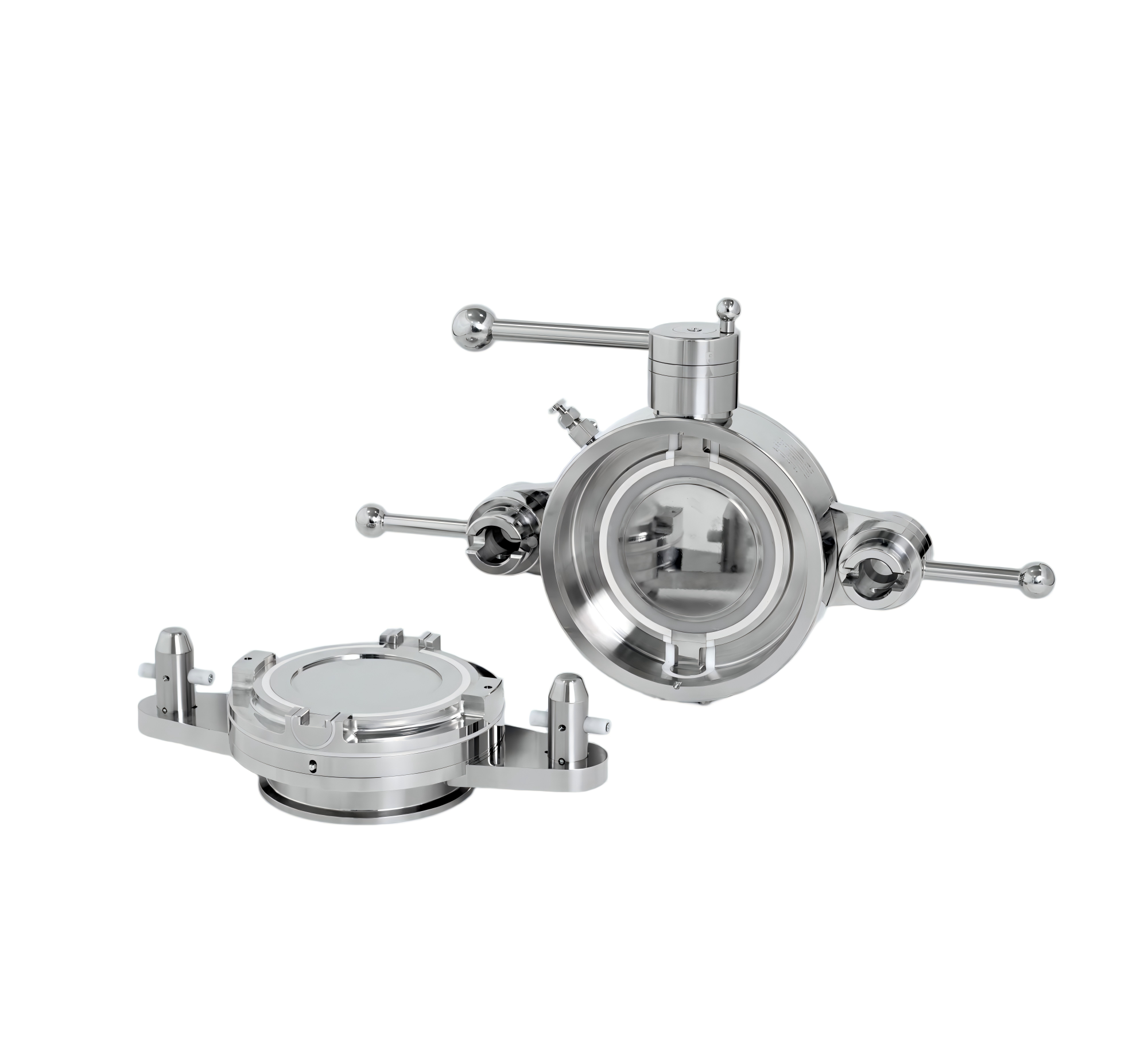
Pressure fluctuations constantly reshape the contact zone between seal faces, creating a delicate balance between leakage control and wear resistance. Rather than treating these variations as mere noise, engineers now view them as a dynamic input that dictates how sealing materials respond over time. The key lies in understanding how micro-gaps open and close under alternating loads, altering the film thickness and interfacial friction in ways that static models fail to capture.
Under severe pressure swings, traditional sealing elements often exhibit hysteresis that leads to unpredictable performance—seals may hold firm during steady-state operation yet leak transiently when pressure drops suddenly. This behavior stems from the viscoelastic recovery of the sealing material, which lags behind the faster fluid pressure changes. By mapping these time-dependent responses, engineers can select elastomers or composite materials with tuned relaxation spectra, ensuring that the seal maintains intimate contact even as the load fluctuates.
Practical mitigation involves more than material choice alone. Groove geometry, squeeze ratio, and surface roughness must be co-optimized to accommodate the full range of expected pressure amplitudes. For instance, a seal designed with a slight axial taper can compensate for the dynamic rocking motion caused by uneven pressure distribution. Ongoing testing with high-frequency pressure pulsations reveals that small geometric adjustments often yield significant improvements in seal life, reducing both blow-by and surface scoring under real-world operating conditions.
The Role of Precision Machining in Leak-Free Operation
Achieving a leak-free system rarely comes down to a single component or a lucky choice of gasket. It starts at the microscopic level, where precision machining defines how two surfaces meet. A flange face with even a few microns of waviness can create tiny channels that fluid eventually finds, no matter how tight the bolts are. High-precision turning, milling, and grinding produce finishes with consistent flatness and controlled roughness, leaving no room for capillary paths. The tolerance stack matters as much as the surface itself—when mating parts are machined to exact dimensions, the seal compression stays uniform around the entire circumference, preventing one side from opening up under thermal cycling or pressure spikes.
Material choice shapes how well machining holds up over time. Softer alloys may be easier to cut, but they can smear or gall during finishing, leaving embedded particles that corrode or create leak channels later. Harder substrates demand slower feeds and sharper tooling, yet they reward the effort with dimensional stability across thousands of operating hours. A skilled machinist also accounts for heat distortion during cutting—excessive tool pressure can warp a thin-walled fitting by a few tenths of a millimeter, enough to compromise a seal once the part cools and returns to room temperature. Stress relieving after rough cuts, followed by finish passes with minimal depth, keeps the geometry true to the print without residual stresses that could relax in service.
In fuel systems, hydraulic manifolds, and semiconductor gas lines, the difference between a nuisance weep and a perfectly dry joint often traces back to details like bore concentricity and thread lead accuracy. A misaligned port can cock the sealing washer, concentrating load on one edge while the opposite side barely touches. Precision boring and single-point threading eliminate this eccentricity, ensuring the seal ring compresses evenly. Some manufacturers now use in-process metrology to verify critical diameters and flatness before the part ever leaves the machine, catching drift that would have gone unnoticed in a final inspection. That kind of closed-loop control turns precision machining from a general principle into a repeatable, documented guarantee against leaks.
Corrosion Resistance: Beyond Basic Coatings
Corrosion resistance often gets reduced to a simple coating choice, but real protection demands more than a thick layer of paint. The base metal, surface preparation, and even micro-roughness all shape how well a part survives humid, salt-laden, or chemically aggressive environments. Overlooking these fundamentals can turn a supposedly protected surface into a hidden weak point.
Advanced solutions now pair multiple barrier mechanisms rather than relying on a single film. Sacrificial primers, conversion layers, and sealants work together to interrupt the electrochemical pathways that drive rust and pitting. This layered logic isn't just about stacking materials—it's about tuning each interface so that any breach stays localized instead of spreading.
Field results show why this matters: components with identical outer finishes can differ by years in service life based on edge treatment alone. Sharp corners, weld zones, and fastener holes act as failure magnets unless addressed during design. Treating corrosion resistance as a system-level trait—not a final spray step—changes the outcome from temporary shine to long-term structural integrity.
Thermal Expansion and Its Impact on Valve Seating
When a valve cycles through large temperature swings, the body and the seat rarely expand at identical rates. A stainless steel body paired with a hardened stellite seat, for instance, can develop a mismatch of several thousandths of an inch at operating temperature. That gap, even if it appears small, directly changes the seating stress and can break the sealing line that was lapped at room temperature.
The damage often shows up first as intermittent leakage during warm-up or cool-down, rather than a steady failure at full temperature. Repeated thermal cycling also promotes fretting at the seat-to-body interface, where small relative movements grind away surface material and create debris that prevents the seat from bedding properly. In severe cases, a seat ring that expands faster than the surrounding pocket can yield plastically and lose its interference fit once the valve cools.
A practical mitigation involves matching thermal expansion coefficients between the seat and its retaining components, or designing a flexible seat that can absorb differential growth without losing contact pressure. For high-temperature services, some users preload the seat with a slight taper or use a gasket material that accommodates expansion while maintaining a tight seal. These choices are rarely standardized because the acceptable amount of differential expansion depends on the specific temperature profile, pressure class, and seat geometry.
Field Data: What Real Installations Reveal About Durability
Real-world performance rarely mirrors lab tests, and that's exactly where field data earns its keep. Installations across coastal rooftops, desert carports, and snowy alpine arrays reveal patterns that accelerated aging chambers simply miss. Corrosion near salt spray, micro-cracking from thermal swings, and unexpected frame fatigue show up years before spec sheets would predict. The takeaway isn't that lab testing is useless—it's that durability claims need ground truth from actual deployments to hold weight.
One standout from recent audits: modules installed in moderate climates often outlast their datasheet warranties by a wide margin, while those in high-UV, high-humidity zones degrade faster than linear models suggest. Junction box failures cluster around specific mounting angles, and backsheet embrittlement appears linked to regional air pollutants, not just sunlight hours. These correlations only become visible when you gather enough site-level data across diverse geographies.
For anyone specifying or financing solar assets, this means leaning less on generic degradation rates and more on comparable field datasets. A 0.5% annual loss assumption might hold for one region but fall apart three hundred miles away. The most reliable durability insights come from operators who track their fleets over time—and share that data openly. That's how the industry moves from guesswork to engineering confidence.
FAQ
A split butterfly valve has a body that is split into two halves, usually along the stem axis, which lets the seat and disc be installed with less deformation. This construction reduces the chance of uneven seat compression, so the valve holds a tighter shut-off and cycles more consistently. In contrast, a one-piece body often requires the seat to be forced in, which can create high spots or localized wear.
For corrosive or aggressive media, many Chinese manufacturers offer bodies in CF8M or duplex stainless steel, with seats in reinforced PTFE or metal. The disc may be coated with PFA or made from a corrosion-resistant alloy. The choice depends on temperature, concentration, and the presence of abrasive solids; some users prefer a PTFE seat for chemical resistance, while others use a metal seat for high-temperature or erosive conditions.
The split body allows the internals to be removed without taking the valve completely out of the pipeline in some installations. Because the body halves separate, the seat can be inspected and replaced with simple tools. This lowers the risk of misalignment during reassembly, which is a common hidden cause of early seal failure in monolithic bodies.
A meaningful factory acceptance test should include a shell test at 1.5 times the rated pressure and a seat leakage test at the rated pressure. For high-cycle applications, a torque test with the actual media or a suitable substitute can expose problems that hydrostatic tests miss, such as stem binding or seat extrusion. Checking the operating torque through the full 90-degree travel is particularly useful.
Eccentricity reduces rubbing between the disc and the seat during the opening and closing strokes. A double eccentric design moves the disc off the seat quickly, lowering wear and operating torque. Triple eccentric adds a conical seating surface that creates a metal-to-metal seal with almost no friction, which suits high-temperature or frequent cycling service where soft seats would degrade.
Rapid temperature changes can cause the body and disc to expand at different rates. In a split body, the bolted joint and seat groove need to accommodate this differential movement without loosening. If the seat material has a high coefficient of thermal expansion, it may extrude or lose compression at low temperatures. That is why some users request seats with filled PTFE or metal backups for thermal cycling.
The most common issues are seat extrusion at high differential pressure, stem leakage from worn packing, and disc misalignment after field reassembly. These can be prevented by specifying a seat with anti-extrusion rings, selecting live-loaded packing or a bellows seal for the stem, and using factory-installed alignment pins or match marks during reassembly. Torque monitoring also helps detect rising friction before a component fails.
Review the material test reports, pressure test certificates, and any third-party inspection reports. Ask for a documented quality plan that includes raw material traceability, machining tolerances, and final assembly checks. A supplier that can provide a detailed dimensional report and a torque curve for each valve is usually more reliable than one that only provides a standard hydrostatic test certificate.
Conclusion
Real-world performance of Chinese split butterfly valves depends on a chain of choices that catalogues rarely capture. Material selection is the starting point: the disc, body, and stem must be compatible not just with the process fluid but with each other, otherwise galvanic or crevice issues appear early. Precision machining of the split body halves is what actually determines whether the sealing faces meet squarely when the valve closes. A few microns of misalignment from tool wear can force the seat to over-compensate, accelerating local wear. Field data from water treatment and chemical plants consistently links early leakage to inconsistent bore geometry and poor surface finish, not just to the base metal grade.
Under fluctuating pressure loads, sealing dynamics change more than static tests suggest. The seat must recover quickly from pressure reversals without taking a permanent set, and thermal expansion adds another variable—if the disc and body grow at different rates, the seating angle shifts and the valve may pass media at high or low temperature extremes. Coatings help, but corrosion resistance is rarely just about adding a thicker layer; edge retention, adhesion after thermal cycling, and coverage in pockets of the split joint matter more. Installations that report multi-year durability tend to use valves where machining tolerances, material pairs, and seat geometry have been designed as one system rather than selected from a spec sheet.
Contact Us
Contact Person: Ananda
Email: [email protected]
Tel/WhatsApp: 8619016718200
Website: https://www.wzaomi.com