

Best Expansion Valve Options for Reliable Cooling and Temperature Control
2026-11-20
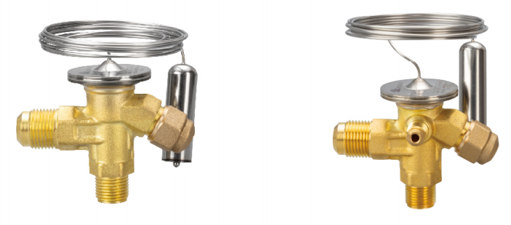
Temperature swings in a cooling system rarely fix themselves. More often, they trace back to an expansion valve that is oversized, undersized, or simply not built for the load it faces every day. A reliable valve does more than open and close — it keeps refrigerant moving at the right rate so coils stay stable and compressors avoid unnecessary strain. In this post, we look at expansion valve options that consistently handle that job, and why HONGSEN has become a name worth checking when precision matters.
Where Sensing Bulb Placement Changes Everything
A sensing bulb gives the control system a picture of the process, but the picture depends entirely on where the bulb sits. Put it at the bottom of a suction line and it may read liquid refrigerant that never fully boiled off. Move it too close to a hot gas line or a warm compressor and it picks up heat that has nothing to do with the load. The control then reacts to a ghost instead of the actual temperature.
Small lines often tolerate a wider range of positions, but larger piping punishes careless placement. On those circuits the bulb belongs on an upper portion of a horizontal run, away from elbows, distributors, and any point where oil or liquid collects during off cycles. The same idea carries over to tanks and air streams: the element has to sit in a mixed, moving zone. A spot that looks convenient but sits in a dead pocket will always deliver lagging or misleading readings.
What makes placement so decisive is timing. A bulb mounted too far upstream or downstream changes when the system sees a temperature shift. That shift shows up as hunting, frost, or poor temperature control long before anyone suspects the sensor location. Moving the bulb a few inches often solves what adjustment screws and charge tweaks cannot.
Valve Capacity Is About Minimum Load, Not Just Full Load
Sizing a control valve around full-load flow misses where most systems actually live. Once a process settles into normal operation, the valve may spend long stretches throttling near the bottom of its stroke. At that point, a high maximum capacity means very little if the valve cannot hold a steady position at low openings without chasing the setpoint.
Minimum controllable flow is often the stricter requirement. Two valves with the same full-load rating can behave completely differently when demand drops to ten or fifteen percent. The trim, plug contour, and actuator resolution start to dominate. If those were chosen only to hit a peak flow number, expect poor control, wire drawing, and seat wear at part load.
A better approach is to start with the lowest sustained load the system is expected to handle, then check whether the valve can control there without excessive gain or deadband. That may lead to a smaller valve, a different characteristic, or a reduced-port trim. The full-load case still gets checked, but it should not be the only number driving the selection.
Why Two Valves With the Same Rating Behave Differently
A shared rating only defines pressure and temperature limits, not the internal shape that actually controls flow. Two valves can carry the same class, size, and even the same Cv while using different plug contours, seat angles, cage hole patterns, or bonnet volumes. Those details change how the fluid accelerates, where turbulence forms, and how much noise or cavitation the valve produces, so the two units may feel and respond very differently under identical service conditions.
Variation also creeps in through materials and assembly. Castings from different heats or suppliers can differ in surface finish, hardness, and clearance, while actuator spring ranges, packing friction, and positioner calibration introduce another layer of behavioral spread. Even two valves built on the same line can drift apart once one has been lapped, adjusted, or run in for a few hundred cycles.
Installation often seals the difference. Upstream disturbances, gasket alignment, pipe strain, and even mounting orientation alter the flow profile entering the valve and the load on its stem. A rating is only a design envelope; it says little about how a specific valve will settle into a specific process, which is why identical nameplates rarely translate into identical field behavior.
Electronic Expansion Valves Under Uneven Load Conditions
In multi-circuit evaporator systems, uneven load distribution pushes electronic expansion valves into operating regions where their control assumptions begin to break down. One circuit may be starved while another runs close to flooding, and the valve reacts to a local superheat signal that no longer represents the full coil. The result is often a repeating cycle of overcorrection and delayed response, with suction superheat hunting instead of settling into a stable band.
A common improvement is to widen the superheat target under partial load and reduce the integral response until the circuit finds a steady rhythm. Distributor and nozzle sizing also needs to match the lowest expected load rather than only the design peak. Where the imbalance is more severe, adding individual circuit pressure regulators or suction stops gives the valve a more predictable boundary, so it is not trying to manage both refrigerant distribution and superheat control at the same time.
Zeotropic refrigerants add another layer of difficulty because evaporator inlet and outlet states do not translate cleanly to a single pressure-based saturation temperature. A valve tuned for mid-range operation can push the circuit into low superheat oscillation after defrost recovery or during sudden case load changes. In those situations, a feed-forward signal tied to compressor capacity or actual circuit load can remove some of the correction burden from the PID loop and keep the valve from chasing transient noise.
Refrigerant Retrofits That Quietly Limit Your Valve Options
A refrigerant retrofit can look like a simple gas swap until the first valve replacement comes due. The trouble is that many existing valves were selected around the chemistry of the original charge. Seals and seat discs that held up under R-22 or R-404A may not tolerate the newer HFO blends, especially when the replacement runs with noticeable temperature glide and different oil carry. What used to be an off-the-shelf valve suddenly becomes a special-order item once you filter for material compatibility and the correct pressure-temperature range.
The physical constraints add another quiet filter. Because the piping is already in place, the new valve must line up with the old flange spacing, port size, and connection type. That removes a large share of the catalog before you even consider capacity. Some options look right on the datasheet but lack the listing for the retrofit refrigerant, and using them anyway can leave you relying on a field workaround rather than a rated assembly.
Over time this narrows the supply chain in ways that are easy to miss during planning. Distributors may stock only a few models rated for the new gas, and lead times jump when a stainless body or a specific elastomer is required. It is often cheaper to verify valve compatibility early than to discover later that a retrofit has quietly limited your service options to a handful of hard-to-find parts.
Superheat Hunting Is a System Signal, Not a Valve Flaw
A hunting superheat reading often gets pinned on the expansion valve, but the valve is rarely the origin of the instability. In most systems, the valve is simply reacting to changes in evaporator load, liquid feed quality, or condensing pressure that have already shifted upstream. The oscillation you see at the gauge is closer to a nervous tic than a broken component—it tells you the system is struggling to settle, not that the valve has lost its mind.
When the signal swings in a regular pattern, start looking at what else is cycling. Condenser fan controls, uneven airflow across the coil, a distributor that is not feeding circuits evenly, or a modest refrigerant charge imbalance can all push the evaporator in ways that make superheat appear unstable. Moisture or non-condensables in the system can also cause the valve to hunt by creating intermittent flash gas at the inlet, which is often misread as a sticking needle or a bad powerhead.
Before condemning the valve, log the superheat alongside suction pressure, liquid subcooling, and any staging events. A strong diagnostic habit is to look for the cadence of the hunting: if it lines up with a fan, a pump, or a load change, that is your source. Fixing the signal means resolving the rhythm behind it, not silencing the component that is only trying to keep up.
FAQ
The bulb on the suction line gives it a direct mechanical response to changes in refrigerant temperature, so it can feed the evaporator without needing a controller or sensors. For a walk-in cooler or prep table with fairly steady loads, a correctly sized TXV holds superheat well and keeps the coil from flooding. Most problems I see come from sloppy bulb mounting or guessing at the setting, not from the basic design.
If the load moves around a lot because of frequent door openings, changing product loads, or big swings in outdoor conditions, an EEV earns its cost. It reads temperature and pressure in real time and adjusts flow faster than a bulb can. You get tighter discharge air control and often better compressor protection during low-load periods. On a small system with stable conditions, the extra setup and wiring are usually overkill.
Yes, and it often happens slowly. Overfeeding lets liquid refrigerant wash back to the compressor, which dilutes oil and can wipe bearings or break valves. Underfeeding leaves the compressor running hot because there is less cool suction gas returning. Before the failure, you may notice high discharge temperatures, oil trips, or frost patterns that never look right. Selecting the correct capacity and refrigerant match is about protecting the compressor as much as cooling performance.
Internal equalization senses pressure at the valve outlet, which is fine for small coils with little pressure drop. On larger evaporators or coils with distributors, the pressure drop across the circuit throws that reading off. An externally equalized valve has a line connected downstream of the evaporator, so it sees the actual outlet pressure and controls superheat more accurately. It is a small plumbing difference, but on the wrong coil an internal valve will hunt and starve sections.
Start with the bulb. It needs to be tight against a horizontal section of the suction line, insulated from the air, and located where it sees a true mixed temperature. Then make superheat changes in small steps and give the system time to settle. If hunting continues, look past the valve. Uneven airflow, a restricted distributor, low charge, or an oversized valve can all cause the same symptom.
Balanced-ported valves tend to be more stable when head pressure drops, because their flow does not swing as much with inlet pressure changes. For wider load swings, an electronic valve paired with the right controller can react to superheat almost continuously. That is useful on systems with variable-speed compressors or cold climate operation. The key is not to oversize the valve to cover every possible condition; that usually makes low-load control worse.
Match the valve to the actual operating conditions, not just the old part number. Confirm the refrigerant, evaporator capacity at the design box temperature, available pressure drop, and whether the original valve used internal or external equalization. Also check the connection style and body size so the replacement fits without adding adapters. If the system has been modified, do not assume the previous valve was sized correctly.
Conclusion
Selecting an expansion valve that holds stable cooling rarely comes down to the catalog rating alone. A thermostatic valve can look correct on paper and still fight the system if the sensing bulb is mounted too close to a fitting, exposed to ambient air, or placed where liquid can pool. The bulb position shifts the superheat signal, so two identical valves often act differently once installed. Capacity also deserves more attention at minimum load than at full load: a valve oversized for light-duty conditions will hunt and flood or starve the evaporator long before maximum capacity is reached. In retrofits, this gets more complicated because a refrigerant change can quietly narrow the usable valve range, especially when lubricant return, pressure drop, or lower mass flow makes an existing orifice or charge unsuitable.
Electronic expansion valves are not an automatic fix, but they help where uneven load conditions make a fixed orifice or conventional TXV struggle. Their advantage is not just precision; it is the ability to keep control stable when one circuit runs lighter than another or airflow changes across the coil. Still, superheat hunting should be read as a system signal rather than an immediate valve defect. Hunting often points to charge imbalance, poor distributor feed, sensor placement, or unstable condensing pressure. The more reliable choice is usually the valve that matches the actual load envelope, can tolerate the chosen refrigerant, and is installed with the sensing element in a location that sees real suction gas. That combination, rather than a higher nominal capacity or a longer feature list, tends to deliver repeatable temperature control.
Contact Us
Contact Person: KOPASS HO
Email: [email protected]
Tel/WhatsApp: 8613606566112
Website: https://www.hongsenref.com/